3-21
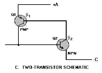
Figure 3-18C.—SCR structure.
In operation the collector of Q2 drives the base of Q1, while the collector of Q1 feeds back to the
base of Q2. (Beta) 1 is the current gain of Q1, and (Beta) 2 is the current gain of Q2. The gain of this
positive feedback loop is their product, 1 times 2. When the product is less than one, the circuit is stable;
if the product is greater than unity, the circuit is regenerative. A small negative current applied to terminal
G will bias the NPN transistor into cutoff, and the loop gain is less than unity. Under these conditions, the
only current that can exist between output terminals A and C is the very small cutoff collector current of
the two transistors. For this reason the impedance between A and C is very high.
When a positive current is applied to terminal G, transistor Q2 is biased into conduction, causing its
collector current to rise. Since the current gain of Q2 increases with increased collector current, a point
(called the breakover point) is reached where the loop gain equals unity and the circuit becomes
regenerative. At this point, collector current of the two transistors rapidly increases to a value limited only
by the external circuit. Both transistors are driven into saturation, and the impedance between A and C is
very low. The positive current applied to terminal G, which served to trigger the self-regenerative action,
is no longer required since the collector of PNP transistor Q1 now supplies more than enough current to
drive Q2. The circuit will remain on until it is turned off by a reduction in the collector current to a value
below that necessary to maintain conduction.
The characteristic curve for the SCR is shown in figure 3-19. With no gate current, the leakage
current remains very small as the forward voltage from cathode to anode is increased until the breakdown
point is reached. Here the center junction breaks down, the SCR begins to conduct heavily, and the drop
across the SCR becomes very low.


