4-48
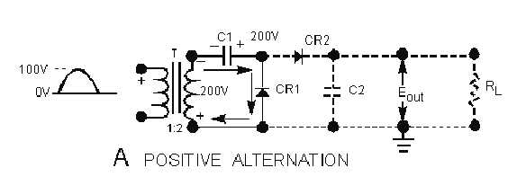
Figure 4-45A.—Rectifier action of CR1 and CR2. POSITIVE ALTERNATION
Notice that C1 and CR1 work exactly like a half-wave rectifier. During the positive alternation of the
input cycle (view A), the polarity across the secondary winding of the transformer is as shown. Note that
the top of the secondary is negative. At this time CR1 is forward biased (cathode negative in respect to the
anode). This forward bias causes CR1 to function like a closed switch and allows current to follow the
path indicated by the arrows. At this time, C1 charges to the peak value of the input voltage, or 200 volts,
with the polarity shown.
During the period when the input cycle is negative, as shown in view B, the polarity across the
secondary of the transformer is reversed. Note specifically that the top of the secondary winding is now
positive. This condition now forward biases CR2 and reverse biases CR1. A series circuit now exists
consisting of C1, CR2, C2, and the secondary of the transformer. The current flow is indicated by the
arrows. The secondary voltage of the transformer now aids the voltage on C1. This results in a pulsating
dc voltage of 400 volts, as shown by the waveform. The effect of series aiding is comparable to the
connection of two 200-volt batteries in series. As shown in figure 4-46, C2 charges to the sum of these
voltages, or 400 volts.
Figure 4-45B.—Rectifier action of CR1 and CR2. NEGATIVE ALTERNATION


