4-45
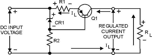
voltage polarity is a result of current flowing through R1, and this negative voltage opposes the forward
bias for Q1. However, since the regulated voltage across CR1 has an opposite polarity, the actual bias of
the transistor is the difference between the two voltages. You should see that the purpose of R2 is to
function as a current-limiting resistor for the Zener diode.
Figure 4-41.—Current regulator.
The purpose of a current regulator is to provide a constant current regardless of changes in the input
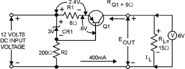
voltage or load current. The schematic shown in figure 4-42 is that of a circuit designed to provide a
constant current of 400 milliamperes. Voltmeters are shown in the schematic to emphasize the voltage
drops across specific components. These voltages will help you understand how the current regulator
operates. The voltage drop across the base-emitter junction of Q1 is 0.6 volt. This voltage is the difference
between the Zener voltage and the voltage drop across R1. The 0.6-volt forward bias of Q1 permits
proper operation of the transistor. The output voltage across RL is 6 volts as shown by the voltmeter. With
a regulated current output of 400 milliamperes, the transistor resistance (RQ1) is 9 ohms. This can be
proved by using Ohm's law and the values shown on the schematic. In this case, current (I) is equal to the
voltage drop (E) divided by the resistance (R). Therefore: 12 volts divided by 30 ohms equals 0.4 ampere,
or 400 milliamperes.
Figure 4-42.—Current regulator (with circuit values).


