4-41
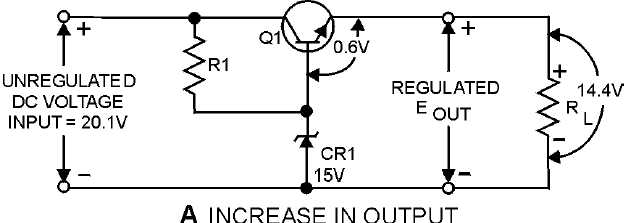
forward bias of Q1 changes to 0.6 volt. Because this bias voltage is less than the normal 0.7 volt, the
resistance of Q1 increases, thereby increasing the voltage drop across the transistor to 5.8 volts. This
voltage drop restores the output voltage to 14.3 volts. The entire cycle takes only a fraction of a second
and, therefore, the change is not visible on an oscilloscope or readily measurable with other standard test
equipment.
Figure 4-36A.—Series voltage regulator. INCREASE IN OUTPUT
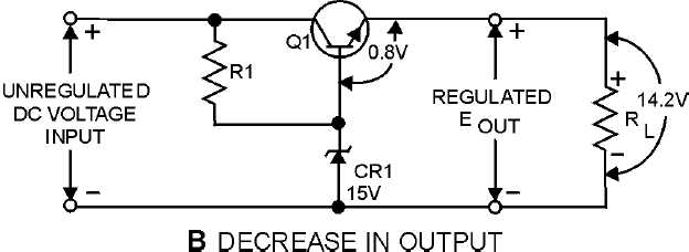
View B is a schematic diagram for the same series voltage regulator with one significant difference.
The output voltage is shown as 14.2 volts instead of the desired 14.3 volts. In this case, the load has
increased causing a lowered voltage drop across R
L
to 14.2 volts. When the output decreases, the forward
bias of Q1 increases to 0.8 volt because Zener diode CR1 maintains the base voltage of Q1 at 15 volts.
This 0.8 volt is the difference between the Zener reference voltage of 15 volts and the momentary output
voltage. (15 V
-
14.2 V = 0.8 V). At this point, the larger forward bias on Q1 causes the resistance of Q1
to decrease, thereby causing the voltage drop across Q1 to return to 5.7 volts. This then causes the output
voltage to return to 14.3 volts.
Figure 4-36B.—Series voltage regulator. DECREASE IN OUTPUT