2-25
In summary, the horizontal line displayed on a CRT or on the face of a television tube is made by
sweeping a stream of electrons rapidly across the face of the CRT. This sweeping action, or scanning, is
performed by rapidly varying the voltage potential on the deflection plates as the electron stream passes.
Vertical Deflection
As we mentioned earlier, a CRT can be used to graphically and visually plot an electronic signal,
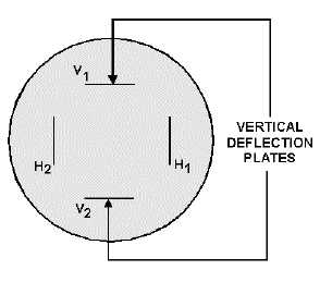
such as a sine wave. This is done by using a second set of deflection plates called VERTICAL-
DEFLECTION PLATES. Examine figure 2-26. You are looking at the front view (facing the screen) of
a CRT, back into the tube at the deflection plates. In normal usage, the horizontal plates sweep a straight
line of electrons across the screen from left to right while the signal to be displayed is applied to the
vertical deflection plates. A circuit of this type is shown in figure 2-27. We will use this figure to explain
how a sine wave is displayed. First, however, you need to understand what is happening in view A. The
box on the left of the CRT labeled HORIZONTAL-DEFLECTION CIRCUITS is an electronic circuit
that will duplicate the actions of R1 and R2 used earlier in making up a horizontal line. How it works will
be discussed in a later NEETS module. Notice T1; the output of this transformer is applied to the vertical-
deflection plates. The signals applied to the vertical plates are 180º out of phase with each other. Thus,
when one plate is attracting the electron beam, the other will be repelling the electron beam. Because you
are only concerned with what happens inside the CRT, this circuitry will be eliminated and only the CRT
and its deflection plates will be shown, as in view B.
Figure 2-26.—Arrangement of deflection plates in a CRT, front view.

