2-26
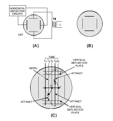
Figure 2-27.—Vertical deflection in a CRT.
Now look at view C. While this illustration looks complicated, don’t let it worry you. You have
already analyzed more complicated diagrams. The sine wave in the center of the screen is the signal that
will be displayed as a result of the two 180º out-of-phase sine waves applied to the vertical-deflection
plates. The five spots on the center sine wave represent the five electrons used to explain horizontal
deflection. Only now these electrons will be deflected both vertically and horizontally. Time lines T1
through T5 represent the time when each like-numbered electron reaches the area of the deflection plates.
Because you already know how the electron beam is swept or deflected horizontally, we will not discuss
horizontal deflection. Just remember that from T1 to T5, the electron beam will be continuously moved
from your left to your right. Now that you know where everything is on the illustration, you are ready to
discover how a sine wave is displayed on a CRT.
At time 1 (T1), the sine waves applied to both vertical-deflection plates are at their null points, or
zero volts. As a result, electron 1 is not vertically deflected and strikes the CRT at its vertical center. At
time 2 (T2), the sine wave applied to the top plate is at its maximum negative value. This repels electron 2
toward the bottom of the CRT. At the same time, the sine wave applied to the bottom plate is at the most
positive value, causing electron 2 to be attracted even further toward the bottom of the CRT. Remember,
the beam is also being moved to the left. As a result, electron 2 strikes the CRT face to the right of and
below electron 1. At time 3 (T3), both sine waves applied to the vertical-deflection plates are again at the
null point, or zero volts. Therefore, there is no vertical deflection and electron 3 strikes the CRT face in


