2-24
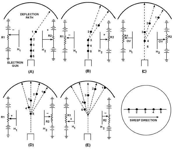
figure 2-25. In view A, five electrons are emitted in sequence, 1 through 5, by the electron gun. The right
deflection plate, H
2, has a large positive potential on it while the left plate, H1 has a large negative
potential on it. Thus, when electron 1 reaches the area of the deflection plates, it is attracted to the right
plate while being repelled from the left plate. In view B, electron 2 has reached the area of the deflection
plates. However, before it arrives, R1 and R2 are adjusted to make the right plate less positive and the left
plate less negative. Electron 2 will still be deflected to the right but not as much as electron 1. In view C,
electron 3 has reached the area of the deflection plates. Before it gets there, R1 and R2 are adjusted to the
mid-point. As a result, both plates have 0 volts applied to them. Electron 3 is not deflected and simply
travels to the center of the CRT screen. In view D, electron 4 has reached the area of the deflection plates.
Notice that R1 and R2 have been adjusted to make the right plate negative and the left plate positive. As a
result, electron 4 will be deflected to the left. Finally, in view E, the left plate is at its maximum positive
value. Electron 5 will be deflected to the extreme left. What you see when you are facing the CRT is a
bright luminous line, as shown in view E. While this description dealt with only five electrons, in reality
the horizontal line across a CRT face is composed of millions of electrons. Instead of seeing five bright
spots in a line, you will see only a solid bright line.
Figure 2-25.—Horizontal deflection.


