3-24
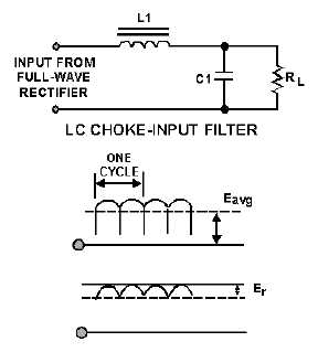
Figure 3-27.—Waveforms for a LC choke-input filter.
The reactance of the inductor (XL) reduces the amplitude of ripple voltage without reducing the dc
output voltage by an appreciable amount. (The dc resistance of the inductor is just a few ohms.)
The shunt capacitor (C1) charges and discharges at the ripple frequency rate, but the amplitude of the
ripple voltage (Er) is relatively small because the inductor (L1) tends to keep a constant current flowing
from the rectifier circuit to the load. In addition, the reactance of the shunt capacitor (XC) presents a low
impedance to the ripple component existing at the output of the filter, and thus shunts the ripple
component around the load. The capacitor attempts to hold the output voltage relatively constant at the
average value of the voltage.
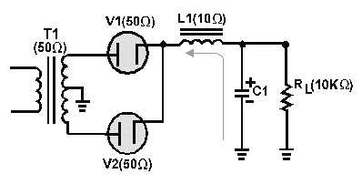
The value of the filter capacitor (C1) must be relatively large to present a low opposition (XC) to the
pulsating current and to store a substantial charge. The rate of the charge for the capacitor is limited by
the low impedance of the ac source (transformer), the small resistance of the diode, and the counter emf
developed by the coil. Therefore, the RC charge time constant (fig. 3-28) is short compared to its
discharge time.
Figure 3-28.—LC choke-input filter (circuit resistance).


