3-20
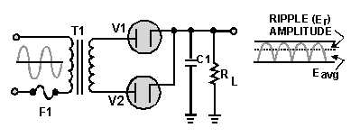
The operation of the simple capacitor filter using a full-wave rectifier is basically the same as the
operation we discussed for the half-wave rectifier. Notice in figure 3-25 that because one of the diodes is
always conducting on either alternation, the filter capacitor charges and discharges during each half cycle.
(Note that each diode conducts only for that portion of time when the peak secondary voltage is greater
than the charge across the capacitor.)
Figure 3-25.—Full-wave rectifier (with capacitor filter).
We stated before that a major advantage of full-wave and bridge rectifiers over half-wave rectifiers is
the ease of filtering their output voltages. You can now see the reason for this. The ripple frequency is
doubled; therefore, the time period the capacitor is allowed to discharge is cut in half. This means that the
capacitor discharges less. Thus, ripple amplitude is less, and a smoother output voltage occurs.
Another thing to keep in mind is that the ripple component (Er) of the output voltage is an ac voltage
and the average output voltage (Eavg) is the dc component of the output. Since the filter capacitor offers a
relatively low impedance to ac, the majority of the ac component flows through the filter capacitor. The
ac component is therefore bypassed (shunted) around the load resistance and the entire dc component (or
Eavg) flows through the load resistance. To clarify this statement, let's take a look at the formula for XC in
a half-wave and full-wave rectifier. First, you must establish some values for the circuit.


