3-28
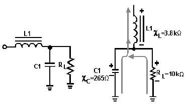
Figure 3-33.—AC component in an LC choke-input filter.
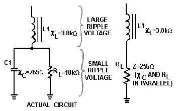
You now have a voltage divider as illustrated in figure 3-34. You should see that because of the
impedance ratios, a large amount of ripple voltage is dropped across L1, and a substantially smaller
amount is dropped across C1 and RL. You can further increase the ripple voltage across L1 by increasing
the inductance:
XL = 2!fL
Figure 3-34.—Actual and equivalent circuits.
Now let's discuss the dc component of the applied voltage. Remember, a capacitor offers an infinite
(") impedance to the flow of direct current. The dc component, therefore, must flow through RL and L1.
As far as the dc is concerned, the capacitor does not exist. The coil and the load are, therefore, in series
with each other. The dc resistance of a filter choke is very low (50 ohms average). Therefore, most of the
dc component is developed across the load and a very small amount of the dc voltage is dropped across
the coil, as shown in figure 3-35.


