3-26
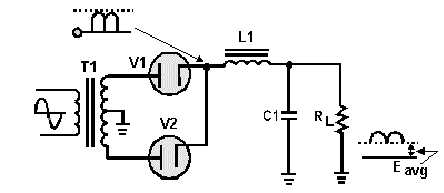
Now look at figure 3-31, which illustrates a complete cycle of operation where a full-wave rectifier
circuit is used to supply the input voltage to the filter. The rectifier voltage is developed across capacitor
C1. The ripple voltage in the output of the filter is the alternating component of the input voltage reduced
in amplitude by the filter section.
Figure 3-31.—Filtering action of an LC choke-input filter.
Each time the plate of a diode goes positive with respect to the cathode, the diode conducts and C1
charges. Conduction occurs twice during each cycle for a full-wave rectifier. For a 60-hertz supply, this
produces a ripple frequency of 120 hertz. Although the diodes alternate (one conducts while the other is
nonconducting), the filter input voltage is not steady. As the plate voltage of the conducting diode
increases (on the positive half of the cycle), capacitor C1 charges-the charge being limited by the
impedance of the secondary transformer winding, the diode's forward (cathode-to-plate) resistance, and
the counter emf developed by the choke. During the nonconducting interval, (when the plate voltage
drops below the capacitor charge voltage), C1 discharges through the load resistance RL. The components
in the discharge path cause a long time constant; thus C1 discharges slower than it charges.
The choke (L1) is usually of a large value, on the order of 1 to 20 henries, and offers a large
inductive reactance to the 120-hertz ripple component produced by the rectifier. Therefore, the effect that
L1 has on the charging of the capacitor (C1) must be considered. Since L1 is connected in series with the
parallel branch consisting of C1 and RL, a division of the ripple ac voltage and the output dc voltage
occurs. The greater the impedance of the choke, the less the ripple voltage that appears across C1 and the
output. The dc output voltage is fixed mainly by the dc resistance of the choke.
Now that you have read how the LC choke-input filter functions, let's take a look at it using actual
component values. For simplicity, the input frequency at the primary of the transformer will be 117 volts
60 hertz. We will use both half-wave and full-wave rectifier circuits to provide the input to the filter.
Starting with the half-wave configuration as shown in figure 3-32, the basic parameters are: with 117
volts ac rms applied to the T1 primary, 165 volts ac peak-to-peak is available at the secondary [(117 V) ×
(1.414) = 165 V]. You should recall that the ripple frequency of this half-wave rectifier is 60 hertz.
Therefore, the capacitive reactance of C1 is:


