3-27
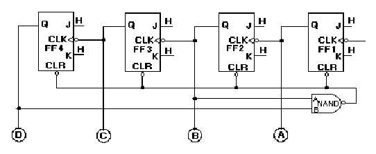
Figure 3-25. —Decade counter.
The counter operates as a normal counter until it reaches a count of 10102, or 1010. At that time, both
inputs to the NAND gate are HIGH, and the output goes LOW. This LOW applied to the CLR input of
the FFs causes them to reset to 0. Remember from the discussion of J-K FFs that CLR and PS or PR
override any existing condition of the FF. Once the FFs are reset, the count may begin again. The
following table shows the binary count and the inputs and outputs of the NAND gate for each count of the
decade counter:
BINARY
COUNT
NAND GATE
INPUTS
NAND GATE
OUTPUT
*******
A
B
*******
0000
0
0
1
0001
0
0
1
0010
1
0
1
0011
1
0
1
0100
0
0
1
0101
0
0
1
0110
1
0
1
0111
1
0
1
1000
0
1
1
1001
0
1
1
1010
1
1
0
Changing the inputs to the NAND gate can cause the maximum count to be changed. For instance, if
FF4 and FF3 were wired to the NAND gate, the counter would count to 11002 (1210), and then reset.
Q43. How many stages are required for a decade counter?
Q44. In figure 3-25, which two FFs must be HIGH to reset the counter?
Ring Counter
A ring counter is defined as a loop of bistable devices (flip-flops) interconnected in such a manner
that only one of the devices may be in a specified state at one time. If the specified condition is HIGH,


