3-30
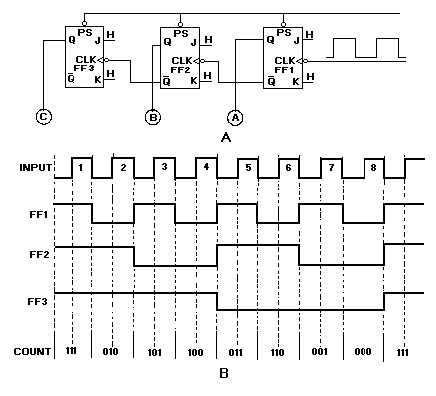
Figure 3-27. —Down counter: A. Logic diagram; B. Timing diagram.
A negative-going pulse is applied to all PS terminals to start the countdown. This causes all the FFs
to set and also lights indicators A, B, and C. The beginning count is 1112 (710). At the same time, LOWs
are applied to the CLK inputs of FF2 and FF3, but they do not toggle because the PS overrides any
change. All actions in the counter will take place on the negative-going portion of the input pulse. Let’s go
through the pulse sequences in figure 3-27, view B.
CP1 causes FF1 to toggle and output Q to go LOW. Lamp A is turned off. Notice that Q goes HIGH
but no change occurs in FF2 or FF3. Lamps B and C are now on, A is off, and the indicated count is 1102
(610).
CP2 toggles FF1 again and lights lamp A. When Q goes HIGH, Q goes LOW. This negative-going
signal causes FF2 to toggle and reset. Lamp B is turned off, and a HIGH is felt at the CLK input of FF3.
The indicated count is 1012 (510); lamps A and C are on, and B is off.
At CP3, FF1 toggles and resets. Lamp A is turned off. A positive-going signal is applied to the CLK
input of FF2. Lamp B remains off and C remains on. The count at this point is 1002 (410).
CP4 toggles FF1 and causes it to set, lighting lamp A. Now FF1, output Q , goes LOW causing FF2
to toggle. This causes FF2 to set and lights lamp B. Output of FF2, Q , then goes LOW, which causes
FF3 to reset and turn off lamp C. The indicated count is now 0112 (310).
The next pulse, CP5, turns off lamp A but leaves B on. The count is now 0102. CP6 turns on lamp A
and turns off lamp B, for a count of 0012. CP7 turns off lamp A. Now all the lamps are off, and the
counter indicates 000.


