3-22
Another method of producing a stable clock pulse is to use a triggered monostable or one-shot
multivibrator. You will recall from NEETS, Module 9, that a one-shot multivibrator has one stable state
and will only change states when acted on by an outside source (the trigger). A block diagram of a
monostable multivibrator with input and output signals is shown in figure 3-21. The duration of the output
pulse is dependent on the charge time of an RC network in the multivibrator. Each trigger input results in
a complete cycle in the output, as shown in figure 3-21. Trigger pulses are supplied by an oscillator.
Figure 3-21. —Monostable multivibrator block diagram.
The circuits described previously are very simple clocks. However, as the complexity of the system
increases, so do the timing requirements. Complex systems have multiphase clocks to control a variety of
operations. Multiphase clocks allow functions involving more than one operation to be completed during
a single clock cycle. They also permit an operation to extend over more than one clock cycle.
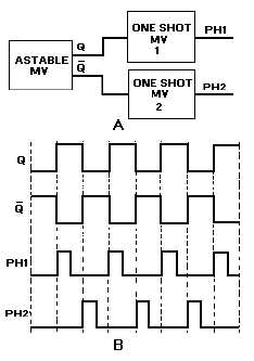
A block diagram of a two-phase clock system is shown in figure 3-22, view A. The astable
multivibrator provides the basic timing for the circuit, while the one-shot multivibrators are used to shape
the pulses. Outputs Q and Q are input to one-shot multivibrators 1 and 2, respectively. The resulting
outputs are in phase with the inputs, but the duration of the pulse is greatly reduced as shown in view B.
Figure 3-22. —Two-phase clock: A. Block diagram; B. Timing diagram.