3-21
CLOCKS AND COUNTERS
Clocks and counters are found in all types of digital equipment. Although they provide different
functions, they are all constructed of circuits with which you are familiar. By changing the way the
circuits are interconnected, we can build timing circuits, multipliers and dividers, and storage units. In this
section we will discuss the purpose, construction, and operation of these important digital circuits.
CLOCKS
Clocks have been mentioned in the preceding section with regard to their action with FFs. You will
recall that the clock is a timing signal generated by the equipment to control operations. This control
feature is demonstrated in both the D and J-K FFs. Remember that the clock output had to be in a certain
condition for the FFs to perform their functions.
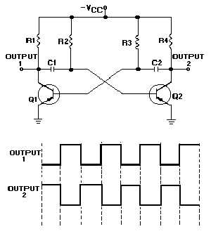
The simplest form of a clock is the astable or free-running multivibrator. A schematic diagram of a
typical free-running multivibrator is shown in figure 3-20 along with its output waveforms. This
multivibrator circuit is called free running because it alternates between two different output voltages
during the time it is active. Outputs 1 and 2 will be equal and opposite since Q1 and Q2 conduct
alternately. The frequency of the outputs may be altered within certain limits by varying the values of
R2C1 and R3C2. You may want to review the operation of the astable multivibrator in NEETS, Module 9,
Introduction to Wave-Generation and Wave-Shaping Circuits. Although the astable multivibrator circuit
seems to produce a good, balanced square wave, it lacks the frequency stability necessary for some types
of equipment.
Figure 3-20. —Free-running multivibrator.
The frequency stability of the astable multivibrator can be increased by applying a trigger pulse to
the circuit. The frequency of the trigger must be higher than the free-running frequency of the
multivibrator. The output frequency will match the trigger frequency and produce a more stable output.