1-18
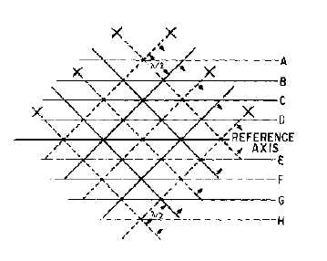
Figure 1-23.—Combined wavefronts.
If two conductive plates are placed along cancellation lines D and E or cancellation lines B and G,
the first boundary condition for waveguides will be satisfied; that is, the E fields will be zero at the
surface of the conductive plates. The second boundary condition is, therefore, automatically satisfied.
Since these plates serve the same purpose as the "b" dimension walls of a waveguide, the "a" dimension
walls can be added without affecting the magnetic or electric fields.
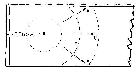
When a quarter-wavelength probe is inserted into a waveguide and supplied with microwave energy,
it will act as a quarter-wave vertical antenna. Positive and negative wavefronts will be radiated, as shown
in figure 1-24. Any portion of the wavefront traveling in the direction of arrow C will rapidly decrease to
zero because it does not fulfill either of the required boundary conditions. The parts of the wavefronts that
travel in the directions of arrows A and B will reflect from the walls and form reverse-phase wavefronts.
These two wavefronts, and those that follow, are illustrated in figure 1-25. Notice that the wavefronts
crisscross down the center of the waveguide and produce the same resultant field pattern that was shown
in figure 1-23.
Figure 1-24.—Radiation from probe placed in a waveguide.