1-17
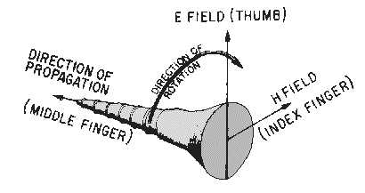
Figure 1-21.—The Poynting vector.
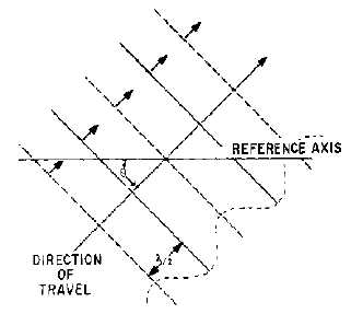
The combined electric and magnetic fields form a wavefront that can be represented by alternate
negative and positive peaks at half-wavelength intervals, as illustrated in figure 1-22. Angle " is the
direction of travel of the wave with respect to some reference axis.
Figure 1-22.—Wavefronts in space.
If a second wavefront, differing only in the direction of travel, is present at the same time, a resultant
of the two is formed. The resultant is illustrated in figure 1-23, and a close inspection reveals important
characteristics of combined wavefronts. Both wavefronts add at all points on the reference axis and cancel
at half-wavelength intervals from the reference axis. Therefore, alternate additions and cancellations of
the two wavefronts occur at progressive half-wavelength increments from the reference axis. In figure
1-23, the lines labeled A, C, F, and H are addition points, and those labeled B, D, E, and G are
cancellation points.