4-48
Q24. Name a common application of counting circuits.
Positive Counters
The POSITIVE-DIODE COUNTER circuit is used in timing or counting circuits in which the
number of input pulses are represented by the output voltage. The output may indicate frequency, count
the rpm of a shaft, or register a number of operations. The counter establishes a direct relationship
between the input frequency and the average dc output voltage. As the input frequency increases, the
output voltage also increases; conversely, as the input frequency decreases, the output voltage decreases.
In effect, the positive counter counts the number of positive input pulses by producing an average dc
output voltage proportional to the repetition frequency of the input signal. For accurate counting, the
pulse repetition frequency must be the only variable parameter in the input signal. Therefore, careful
shaping and limiting of the input signal is essential for you to ensure that the pulses are of uniform width
and that the amplitude is constant. When properly filtered and smoothed, the dc output voltage of the
counter may be used to operate a direct reading indicator.
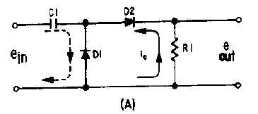
Solid-state and electron-tube counters operate in manners similar to each other. The basic solid-state
(diode) counter circuit is shown in view (A) of figure 4-43. Capacitor C1 is the input coupling capacitor.
Resistor R1 is the load resistor across which the output voltage is developed. For the purpose of circuit
discussion, assume that the input pulses (shown in view (B)) are of constant amplitude and time duration
and that only the pulse repetition frequency changes. At time T0, the positive-going input pulse is applied
to C1 and causes the anode of D2 to become positive. D2 conducts and current ic flows through R1 and
D2 to charge C1. Current ic, develops an output voltage across R1, shown as eout.
Figure 4-43A.—Positive-diode counter and waveform.