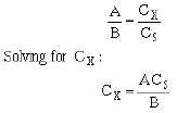
1-17
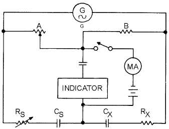
Figure 1-12.—Simplified capacitance bridge.
It is actually the capacitive reactance, rather than the capacitance, that is balanced in this circuit.
In addition to its reactive properties, the capacitor under test always exhibits some loss. This loss
may have the characteristics of either a shunt or series resistance, or it may be a combination of both.
Regardless of its true nature, the loss can always be represented as a simple series resistance, which is
shown in figure 1-12 as R
X. This loss is balanced by the calibrated resistor R
S. Rather than calibrate this
control in terms of resistance, it is convenient to calibrate it in terms of the dissipation factor (the ratio of
the energy dissipated to the energy stored in a capacitor). The RS control then provides the means for
completing the capacitance balance, and its dial reading indicates a loss figure for the capacitor under test.
Q-13.
Which is more accurate, the bridge- or reactance-type meter?
REACTANCE-TYPE MEASUREMENTS
The reactance type of capacitance measuring equipment makes use of the following principle: If an
ac voltage (usually 6.3 volts) at a fixed frequency is applied across a capacitor and resistor in series, the
voltage drop produced across the reactance of the capacitor by the resulting current flow is inversely
proportional to the capacitance. The voltage drop is used to actuate a meter that is calibrated in
capacitance values. This test equipment gives approximate values only and, like the ohmmeter, is used
mostly when portability and speed are more important than precision. The accuracy of the reactance-type
measurement is less for capacitors that have a high power factor. In capacitors with high power factors,
the losses incurred effectively place a certain amount of resistance in series with the capacitive reactance.
The effect of this resistance, when the capacitor is measured, is to cause a greater voltage drop across the
capacitor. This drop is not because of the reactance above, but is the result of the impedance, which of


