1-20
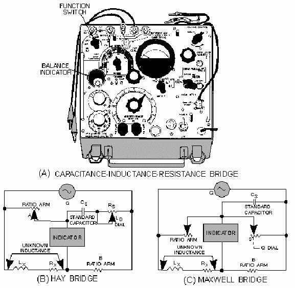
Figure 1-14.—Bridge circuits.
The Hay bridge (view B of fig. 1-14) measures inductance by comparing it with a capacitance; it
differs from the Maxwell bridge (view C) in that the resistance associated with the capacitance is a series
instead of a shunt resistance. The inductance balance depends upon the losses (Q) of the inductor. The
Hay bridge is used for inductors with low losses low D dial reading or high Q) at 1 kilohertz. This circuit
is in effect when the FUNCTION switch is turned to the L(D) position. For a D dial reading up to 0.05,
the error is 0.25%. Above this point the error increases rapidly and affects the basic accuracy of the test
equipment. This limitation is expressed on the front panel of the test equipment as follows: IF D>0.05 ON
L(D)—REBALANCE ON L(Q) . In other words, if the dissipation of an inductor, as read on the D dial
when using the Hay bridge (FUNCTION switch set to L(D) position), exceeds 0.05, then you should
change to the Maxwell bridge (FUNCTION switch set to L(Q) position), which is discussed in the
following paragraph. The loss factor of the inductor under test is then balanced in terms of the Q of the
inductor.
Q-15.
A Hay bridge measures inductance by comparing an inductor to what component?


