3-4
characteristics, which must be subtracted from the total measurement. Hence, the most serious errors
affecting accuracy of a measurement are because of the connecting leads.
Stray wiring capacitance and inductance, called residuals, that exist between the branches of the
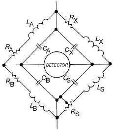
bridge also cause errors. The resistance-ratio bridge, for example, is redrawn in figure 3-3 to show the
interfering residuals that must be eliminated or taken into consideration. Fortunately, these residuals can
be reduced to negligible proportions by shielding and grounding. A method of shielding and grounding a
bridge circuit to reduce the effects of interfering residuals is through the use of a Wagner ground, as
shown in figure 3-4. Observe that with switch S in position Y, the balanced condition can be obtained by
adjusting Z1 and Z2. With switch S in position X, the normal method of balancing the bridge applies. You
should be able to reach a point where there is no deflection of the meter movement for either switch
position (X or Y) by alternately adjusting Z1 and Z2 when the switch is at position Y and by adjusting RS
when the switch is at position X. Under these conditions, point 1 is at ground potential; and the residuals
at points 2, 3, and 4 are effectively eliminated from the bridge. The main disadvantage of the Wagner
ground is that two balances must be made for each measurement. One is to balance the bridge, and the
other is to balance the Wagner ground. Both adjustments are interacting because RA and RB are common
to both switch positions X and Y.
Figure 3-3.—Resistance-ratio bridge residual elements.

