3-9
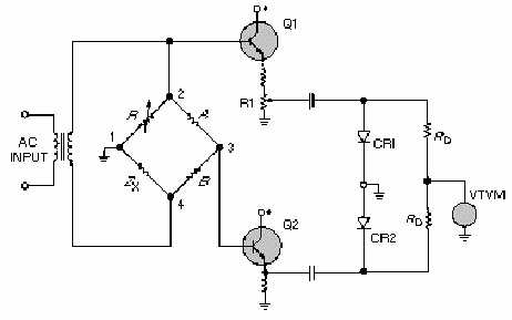
Figure 3-6.—Typical vector-bridge configuration (phase).
CONSTANT-CURRENT, IMPEDANCE-MEASURING TECHNIQUE
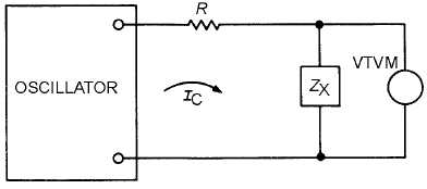
This technique employs an oscillator circuit and a vtvm, as shown in figure 3-7.
Figure 3-7.—Constant-current, impedance-measuring method.
A large value of resistance, R, is selected so that IC is virtually independent of the range of Z
X
to be
measured. Thus, ICZ
X
represents the value of voltage measured by the vtvm. If R is chosen so that the
voltage drop across ZX corresponds to a full-scale reading on the vtvm, a direct reading impedance meter
is realized. For example, assume that the audio oscillator open-circuit voltage is 10 volts (rms) and that
the full-scale reading of the vtvm is 0.05 volt. If you want to measure ZX values ranging up to a maximum
of 5,000 ohms, you should use a 1-megohm resistor for R. This will result in a full-scale, 0.05-volt
deflection. An oscillator that does not produce harmonics should be used.
IMPEDANCE-ANGLE METER
Like vector bridges, impedance-angle meters determine an unknown impedance in terms of
magnitude and phase angle. However, a non-bridge technique is used. The simplified circuit of a
commercial instrument is shown in figure 3-8. With switches S1 and S2 at the BAL position, the variable


