2-9
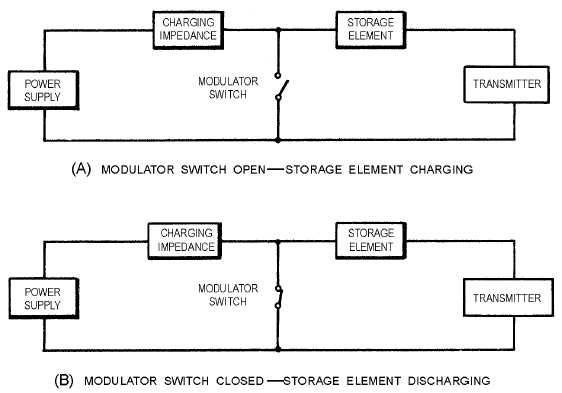
Figure 2-4.—Basic line-pulsing modulator block diagram.
View A of figure 2-4 shows the modulator switch open and the storage element charging. With the
modulator switch open, the transmitter produces no power output, but the storage element stores a large
amount of energy. View B shows the modulator switch closed and the storage element discharging
through the transmitter. The energy stored by the storage element is released in the form of a high-power,
dc modulator pulse. The transmitter converts the dc modulator pulse to an rf pulse, which is radiated into
space by the radar antenna. Thus, the modulator switch is closed for the duration of a transmitted rf pulse,
but open between pulses.
Many different kinds of components are used in radar modulators. The power supply generally
produces a high-voltage output, either alternating or direct current. The charging impedance may be a
resistor or an inductor. The storage element is generally a capacitor, an artificial transmission line, or a
pulse-forming network. The modulator switch is usually a thyratron.
Modulator Storage Element
Capacitor storage elements are used only in modulators that have a dc power supply and an electron-
tube modulator switch.
The capacitor storage element is charged to a high voltage by the dc power supply. It releases only a
small part of its stored energy to the transmitter. The electron-tube modulator switch controls the charging
and discharging of the capacitor storage element.
The artificial transmission line storage element, shown in view A of figure 2-5, consists of identical
capacitors (C) and inductors (L) arranged to simulate sections of a transmission line. The artificial
transmission line serves two purposes: (1) to store energy when the modulator switch is open (between


