2-6
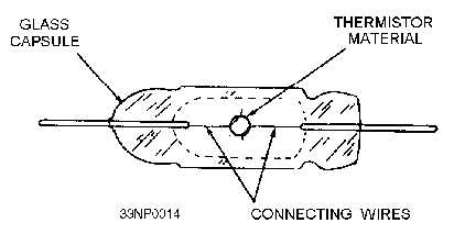
active material is shaped in the form of a bead. It is supported between two pigtail leads by connecting
wires. The pigtail ends are embedded in the ends of the surrounding glass capsule.
Figure 2-3.—Bead-type thermistor.
The negative-resistance temperature coefficient of thermistors is desirable. This is because excessive
power has the effect of changing the resistance of the thermistor to an extent that causes a pronounced rf
mismatch. The resulting decrease in power transfer reduces the likelihood of burnout.
Thermistor Bridge
Figure 2-4, views A and B, is an example of a THERMISTOR BRIDGE used for rf power
measurements. A thermistor bridge circuit includes other thermistor elements, referred to as
compensating thermistors. These thermistors respond to fluctuations in ambient temperature so that the
bridge balances and calibration are maintained over a wide temperature range. Compensating thermistors
are usually in disc form so that they can be mounted on a flat metal surface, such as a chassis or a
waveguide. The thermistor bridge in view B is located in the terminating section of a waveguide and
contains RT-2, a bead thermistor, and two compensating thermistors, RT-1 and RT-3, on the outside of
the waveguide (view A). RA-1 in view B, a calibrated attenuator, controls the amount of rf energy applied
to RT-2.


