2-11
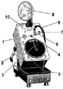
Figure 2-7.—Electronic strobotac.
Table 2-1.—Strobotac Controls and Indicators
CONTROLS AND INDICATORS (see figure 2-7)
NO
NAME
USE
1.
POWER switch
Turns power on and off.
2.
RPM control
Controls the flashing rate of light as the fluted rim is rotated.
Dial is calibrated directly in revolutions per minute (rpm).
3.
Range switch
Selects any of three rpm (internal oscillator) ranges, plus three
external-input positions:
Rpm ranges Intensity External input
110-690 rpm High 700 rpm max
170-4170 rpm Med 4000 rpm max*
4000-25,000 rpm Low 25,000 rpm max
4.
CALibration indicator lamp
Indicates the correct setting of CALibration adjustments for
calibrating the RPM dial to power-line frequency.
5.
HIGH CAL, LOW CAL
Calibration adjustments used to calibrate the RPM dial.
6.
OUTPUT TRIGGER jack
A trigger pulse is available at this jack for strobotac types
1531, 1538, stroboslave type 1539, and strobolume type 1532.
7.
INPUT jack
Used for connecting the stroboscope to an external
synchronizing signal from the electrical device or mechanical
contactor.
8.
Reflector-lamp assembly
Produces and aims the flashing light.
9.
Power cord
A permanently attached 6-foot power cord. For storage, the
cord is wound clockwise around the range-switch knob and
reflector. The plug is secured by sliding it onto the holding
pin.
10.
Holder pin
Used to secure the plug-end of the power cord when unit is to
be stored in its case.
* Flashes at 3600 rpm until external signal is plugged in.


