4-9
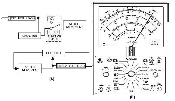
functional block diagram of the ac and output voltage circuits in the multimeter. View B shows the jacks
and switch positions used to measure ac voltages.
Figure 4-6.—Functional block diagram of ac and output voltage circuits.
Measuring Output Voltages
You will often measure the ac component of an output voltage where both ac and dc voltage levels
exist. This occurs primarily in amplifier circuits.
The multimeter has a 0.1-microfarad, 400-volt blocking capacitor in series with the OUTPUT jack.
The capacitor blocks the dc component of the current in the circuit under test, but allows the ac
component to pass on to the indicating circuits.
CAUTION
When using OUTPUT, do not attempt to use the meter in a circuit in which the
dc voltage component exceeds the 400-volt rating of the blocking capacitor.
To use the multimeter to measure output voltage, you must follow these steps:
1.
Set the function switch to AC.
2.
Plug the black test lead into the COMMON jack and the red test lead into the OUTPUT jack.
3.
Set the range switch at the appropriate range position, marked as 2.5V, 10V, 50V, or 250V.
4.
Connect the test leads to the component being measured with the black test lead to the negative
side of the component.


