4-14
The signal conditioning section provides a dc analog voltage, characteristic of the applied input, to
the analog-to-digital converter section. This task is accomplished by the input voltage divider, current
shunts, ac converter, active filter, and associated switching.
The analog-to-digital (a/d) converter section changes the dc output voltage from the signal
conditioning section to digital information. The a/d converter uses a voltage-to-frequency conversion
technique. A dc voltage at the input of the a/d converter is changed to a frequency by the analog
integrated circuit (ic). This frequency is characteristic of the magnitude and polarity of the dc input
voltage. Counting of the output frequency from the analog ic is accomplished by the digital ic. The
resulting count is transferred in binary format to the display section. (Binary number systems are covered
in NEETS, Module 13, Introduction to Number Systems, Boolean Algebra, and Logic Circuits.)
The display section takes the digital (binary) information from the a/d converter section, decodes it,
and visually displays it. The decoded digital information is displayed on numerical LED readouts.
Q-7. In an electronic digital multimeter, the digital information is displayed by what type of numerical
readouts?
Accessories
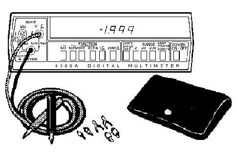
Several accessories are available for use with the electronic digital multimeter. One accessory is the
test lead kit, shown in figure 4-10. The kit contains two color-coded test leads with threaded adapters.
These adapters attach to banana plugs, pin tips, test prod tips, alligator clips, and binding post lugs.
Figure 4-10.—Test lead kit.
Figure 4-11 shows a high-current probe. This probe extends the ac current measurement capability
from 2 to 600 amperes at frequencies up to 400 hertz.


