4-4
The meter leads must make good electrical contact with the resistor leads. Points of contact
should be checked for dirt, grease, varnish, paint or any other material that may affect current
flow.
Touch only the insulated portions of the test leads. Your body has a certain amount of resistance,
which the ohmmeter will measure if you touch the uninsulated portions of the leads.
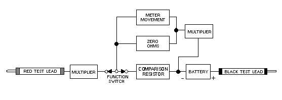
Figure 4-2 is a functional block diagram of the ohmmeter circuit in a VOM. The proper method of
checking a resistor is to connect the red lead to one end of the resistor and the black lead to the other end
of the resistor.
Figure 4-2.—Functional block diagram of an ohmmeter circuit.
Because zero resistance causes full-scale deflection, you should realize that the deflection of the
meter is inversely proportional to the resistance being tested; that is, for a small resistance value, the
deflection will be nearly full scale; and for a large resistance value, the deflection will be considerably
less. This means that the left portion of the OHMS scale represents high resistance; the right side of the
scale represents low resistance. Zero resistance (a short circuit) is indicated on the extreme right side of
the scale; infinite resistance (an open circuit) is located on the extreme left side of the scale.
Notice that you read the OHMS scale on the multimeter from RIGHT to LEFT. For example, the
pointer of the multimeter in figure 4-3 indicates 8.0 ohms. To determine the actual value of a resistor,
multiply the reading on the meter scale by the range switch setting (R 1, R 100, or R 10,000).


