5-4
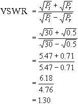
The example above results in a standing wave ratio expressed as 1.3 to 1. In a perfectly matched
transmission line where there is no reflected power (Pr = 0), the standing wave ratio would be 1 to 1. A
standing wave ratio of 1.5 to 1 indicates a 5-percent reflection of energy (loss) and is considered to be the
maximum allowable loss. So, our example is within allowable limits.
If the standing wave ratio is greater than 1.5 to 1, then the transmission line efficiency has decreased
and troubleshooting is necessary. An excellent discussion of the reasons for standing wave ratio increases
is presented in EIMB, Test Methods and Practices, NAVSEA 0967-LP-000-0130.
You can determine the rf power absorbed by the load simply by subtracting the reflected power
reading from the incident power reading made by the wattmeter (30 watts - 0.5 watts = 29.5 watts).
The power meter just discussed is often described as an IN-LINE POWER METER because readings
are taken while the power meter is connected in series with the transmission line. Another type of power
meter used by the Navy measures power indirectly. An example of an indirect-measuring power meter is
described in the next section.
INDIRECT-MEASURING POWER METERS
An example of an indirect-measuring power meter is the HP-431C, shown in figure 5-2. The
controls, connectors, and indicators for the power meter are illustrated in figure 5-3. This power meter can
be operated from either an ac or dc primary power source. The ac source can be either 115 or 230 volts at
50 to 400 hertz. The dc source is a 24-volt rechargeable battery. Overall circuit operation of the power
meter is shown in the block diagram in figure 5-4.


