5-2
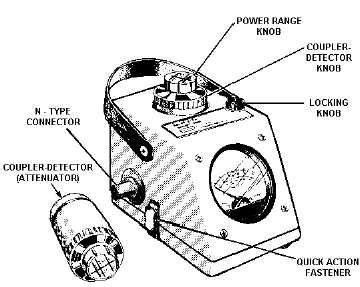
Figure 5-1.—Wattmeter (AN/URM-120).
Other types of power meters measure power indirectly; that is, they sample power in other ways—
but not by being placed directly between the output of the transmitter and the load. Let's discuss the
direct-measuring power meter first; then we'll talk about an indirect-measuring power meter.
DIRECT-MEASURING POWER METERS
The direct-measuring power meter is designed to measure incident (forward) and reflected (reverse)
rf power from 50 to 1,000 watts at 2 MHz to 30 MHz and 10 to 500 watts at 30 MHz to 1,000 MHz.
Three separate COUPLER-DETECTORS (sometimes called ATTENUATORS), each rated to cover a
portion of the frequency and power ranges, are provided with the wattmeter. These devices couple the rf
signal into the wattmeter and detect the signal. The coupler-detector knob projects through the top of the
wattmeter case, as shown on the AN/URM-120 wattmeter in figure 5-1.
A nameplate on the top of the POWER RANGE knob indicates the power range. The POWER
RANGE knob can be rotated 360º to the desired power range. The coupler-detector rotates 180º inside the
metal case for either forward or reverse power measurements. Also located inside the metal case are the
indicating meter and cable for interconnecting the meter to the coupler-detector. The LOCKING knob
locks the coupler-detector and POWER RANGE knobs in place.
Two N-TYPE connectors (one male and one female) are located on either side of the wattmeter case
to connect the instrument between the power source and the load. The upper and lower parts of the
wattmeter are held together with quick-action fasteners, which permit easy access to the inside of the
wattmeter.
Power measurements are made by inserting the proper coupler-detector and connecting the
wattmeter in the transmission line between the load and the rf power source. To measure incident power
with the wattmeter, rotate the arrow on the COUPLER-DETECTOR knob toward the load, and position
the POWER RANGE knob for peak meter reading. To measure reflected power, position the arrow
toward the rf power source.
In effect, rotating the coupler-detector causes the coupler to respond only to a wave traveling in a
particular direction, either to (incident) or from (reflected) the load. It will be unaffected by a wave
traveling in the opposite direction. A diode rectifier in the coupler rectifies the energy detected by the


