1-26
You should recall from NEETS, Module 13, Introduction to Number Systems, Boolean Algebra, and
Logic Circuits, that a basic flip-flop is a device having two stable states and two input terminals (or types
of input signals), each of which corresponds to one of the two states. The flip-flop remains in one state
until caused to change to the other state by application of an input voltage pulse.
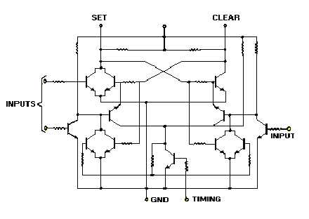
A J-K flip-flop differs from the basic flip-flop because it has a third input terminal. A clock pulse, or
trigger, is usually applied to this input to ensure proper timing in the circuit. An input signal must occur at
the same time as the clock pulse to change the state of the flip-flop. The conventional J-K flip-flop circuit
in figure 1-28 requires approximately 40 discrete components, 200 connections, and 300 processing
operations. Each of these 300 operations (seals and connections) represents a possible source of failure. If
all the elements of this circuit are integrated into one chip of silicon, the number of connections drops to
approximately 14. This is because all circuit elements are intraconnected inside the package and the 300
processing operations are reduced to approximately 30. Figure 1-29 represents a size comparison of a
discrete J-K circuit and an integrated circuit of the same type.
Figure 1-28.—Schematic diagram of a J-K flip-flop.