1-22
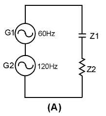
time and compute the sine-wave voltage developed across each impedance for that generator input. Then,
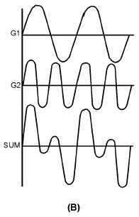
combine the instantaneous voltages (caused by each generator input) to obtain the complex waveform
across each impedance. The nature of the impedance (resistive or reactive) will determine the shape of the
complex waveform. Because the complex waveform is the sum of two individual sine waves, the
composite waveform contains only the two original frequencies.
Figure 1-15A.—Sine-wave generators with different frequencies and linear impedances.
Figure 1-15B.—Sine-wave generators with different frequencies and linear impedances.
Linear impedances may alter complex waveforms, but they do not produce new frequencies. The
output of one generator does not influence the output of the other generator.
TWO SINE WAVE GENERATORS AND A COMBINATION OF LINEAR AND NONLINEAR
IMPEDANCES
Figure 1-16 illustrates a circuit that contains two sine-wave generators (G1 and G2), linear
impedance Z1, and nonlinear impedance Z2, in series. When a single sine-wave voltage is applied to a


