1-23
combined linear and nonlinear impedance circuit, the voltages developed across the impedances are
complex waveforms.
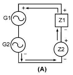
Figure 1-16.—Sine-wave generators with a combination of impedances.
When two sine wave voltages are applied to a circuit, as in figure 1-16, nonlinear impedance Z2
reshapes the two sine-wave inputs and their harmonics, resulting in a very complex waveform.
Assume that nonlinear impedance Z2 will allow current to flow only when the sum of the two
sine-wave generators (G1 and G2) has the polarity indicated. The waveforms present across the linear
impedance will appear as a varying waveform. This will be a complex waveform consisting of:
a dc level
the two fundamental sine wave frequencies
the harmonics of the two fundamental frequencies
the sum of the fundamental frequencies
the difference between frequencies
The sum and difference frequencies occur because the phase angles of the two fundamentals are
constantly changing. If generator G1 produces a 10-hertz voltage and generator G2 produces an 11-hertz
voltage, the waveforms produced because of the nonlinear impedance will be as shown in the following
list:
a 10-hertz voltage
an 11-hertz voltage
harmonics of 10 hertz and 11 hertz (the higher the harmonic, the lower its strength)
the sum of 10 hertz and 11 hertz (21 hertz)
the difference between 10 hertz and 11 hertz (1 hertz)


