1-25
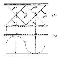
Figure 1-33.—Crisscrossing wavefronts and the resultant E field.
The dominant mode is the most efficient mode. Waveguides are normally designed so that only the
dominant mode will be used. To operate in the dominant mode, a waveguide must have an "a" (wide)
dimension of at least one half-wavelength of the frequency to be propagated. The "a" dimension of the
waveguide must be kept near the minimum allowable value to ensure that only the dominant mode will
exist. In practice, this dimension is usually 0.7 wavelength.
Of the possible modes of operation available for a given waveguide, the dominant mode has the
lowest cutoff frequency. The high-frequency limit of a rectangular waveguide is a frequency at which its
"a" dimension becomes large enough to allow operation in a mode higher than that for which the
waveguide has been designed.
Waveguides may be designed to operate in a mode other than the dominant mode. An example of a
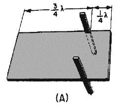
full-sine configuration mode is shown in figures 1-34A and 1-34B. The "a" dimension of the waveguide
in this figure is one wavelength long. You may assume that the two-wire line is 1/4! from one of the "b"
walls, as shown in figure 1-34A. The remaining distance to the other "b" wall is 3/4!. The three-quarter
wavelength section has the same high impedance as the quarter-wave section; therefore, the two-wire line
is properly insulated. The field configuration shows a complete sine-wave pattern across the "a"
dimension, as illustrated in figure 1-34B.
Figure 1-34A.—Waveguide operation in other than dominant mode.


