1-24
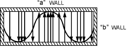
Figure 1-31.—One and one-half sine E field distribution.
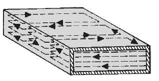
The magnetic field in a rectangular waveguide is in the form of closed loops parallel to the surface of
the conductors. The strength of the magnetic field is proportional to the electric field. Figure 1-32
illustrates the magnetic field pattern associated with a half-sine electric field distribution. The magnitude
of the magnetic field varies in a sine-wave pattern down the center of the waveguide in "time phase" with
the electric field. TIME PHASE means that the peak H lines and peak E lines occur at the same instant in
time, although not necessarily at the same point along the length of the waveguide.
Figure 1-32.—Magnetic field caused by a half-sine E field.
An electric field in a sine-wave pattern also exists down the center of a waveguide. In figure 1-33,
view (A), consider the two wavefronts, C and D. Assume that they are positive at point 1 and negative at
point 2. When the wavefronts cross at points 1 and 2, each field is at its maximum strength. At these
points, the fields combine, further increasing their strength. This action is continuous because each wave
is always followed by a replacement wave. Figure 1-33, view (B), illustrates the resultant sine
configuration of the electric field at the center of the waveguide. This configuration is only one of the
many field patterns that can exist in a waveguide. Each configuration forms a separate mode of operation.
The easiest mode to produce is called the DOMINANT MODE. Other modes with different field
configurations may occur accidentally or may be caused deliberately.


