1-44
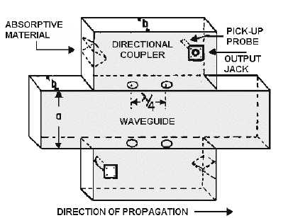
Figure 1-57.—Bidirectional coupler.
Q-45. What is the primary purpose of a directional coupler?
Q-46. How far apart are the two holes in a simple directional coupler?
Q-47. What is the purpose of the absorbent material in a directional coupler?
Q-48. In a directional coupler that is designed to sample the incident energy, what happens to the two
portions of the wavefront when they arrive at the pickup probe?
Q-49. What happens to reflected energy that enters a directional coupler that is designed to sample
incident energy?
Cavity Resonators
In ordinary electronic equipment a resonant circuit consists of a coil and a capacitor that are
connected either in series or in parallel. The resonant frequency of the circuit is increased by reducing the
capacitance, the inductance, or both. A point is eventually reached where the inductance and the
capacitance can be reduced no further. This is the highest frequency at which a conventional circuit can
oscillate.
The upper limit for a conventional resonant circuit is between 2000 and 3000 megahertz. At these
frequencies, the inductance may consist of a coil of one-half turn, and the capacitance may simply be the
stray capacitance of the coil. Tuning a one-half turn coil is very difficult and tuning stray capacitance is
even more difficult. In addition, such a circuit will handle only very small amounts of current.
NEETS, Module 10, Introduction to Wave Propagation explained that a 1/4! section of transmission
line can act as a resonant circuit. The same is true of a 1/4! section of waveguide. Since a waveguide is
hollow, it can also be considered as a RESONANT CAVITY.
By definition, a resonant cavity is any space completely enclosed by conducting walls that can
contain oscillating electromagnetic fields and possess resonant properties. The cavity has many


