4-33
elements that may be used. The construction problem increases with the number of elements, especially
when they are polarized horizontally.
Q32. What is the primary cause of broadside arrays losing efficiency when not operating at their
designed frequency?
Q33. When more than two elements are used in a broadside array, how are the elements arranged?
Q34. As the spacing between elements in a broadside array increases, what is the effect on the major
lobes?
End-Fire Arrays
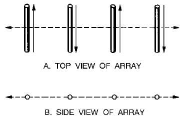
An end-fire array looks similar to a broadside array. The ladder-like appearance is characteristic of
both (fig. 4-28, view A). The currents in the elements of the end-fire array, however, are usually 180
degrees out of phase with each other as indicated by the arrows. The construction of the end-fire array is
like that of a ladder lying on its side (elements horizontal). The dipoles in an end-fire array are closer
together (1/8-wavelength to 1/4 -wavelength spacing) than they are for a broadside array.
Figure 4-28.—Typical end-fire array.
Closer spacing between elements permits compactness of construction. For this reason an end-fire
array is preferred to other arrays when high gain or sharp directivity is desired in a confined space.
However, the close coupling creates certain disadvantages. Radiation resistance is extremely low,
sometimes as low as 10 ohms, making antenna losses greater. The end-fire array is confined to a single
frequency. With changes in climatic or atmospheric conditions, the danger of detuning exists.
RADIATION PATTERN.—The radiation pattern for a pair of parallel half-wave elements fed 180
degrees out of phase is shown in figure 4-29, view A. The elements shown are spaced 1/2 wavelength
apart. In practice, smaller spacings are used. Radiation from elements L and M traveling toward point P
begins 180 degrees out of phase. Moving the same distance over approximately parallel paths, the
respective wavefronts from these elements remain 180 degrees out of phase. In other words, maximum
cancellation takes place in the direction of P. The same condition is true for the opposite direction (toward
P1). The P to P1 axis is the line of least radiation for the end-fire array.


