3-28
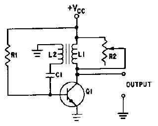
Figure 3-35.—Circuit damping.
When an external resistance is placed across a tank, the formula for the Q of the tank circuit is
Q = R/XL, where R is the equivalent total circuit resistance in parallel with L. You should be able to see
from the equation that the Q is directly proportional to the damping resistance (R). In figure 3-35,
damping resistor R2 is used to adjust the Q which reduces the amplitude of overshoot parasitic
oscillations. As R2 is varied from infinity toward zero, the decreasing resistance will load the transformer
to the point that pulse amplitude, pulse width, and prf are affected. If reduced enough, the oscillator will
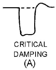
cease to function. By varying R2, varying degrees of damping can be achieved, three of which are shown
in figure 3-36, view (A), view (B and view (C).
Figure 3-36A.—Waveform damping. CRITICAL DAMPING.


