3-25
Simple Series RL Circuit
When S1 is closed in the series RL circuit (view (B) of figure 3-31) L acts as an open at the first
instant as source voltage appears across it. As current begins to flow, EL decreases and ER and I increase,
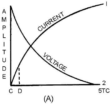
all at exponential rates. Figure 3-32, view (A), shows these exponential curves. In a time equal to 5 time
constants the resistor voltage and current are maximum and EL is zero. This relationship is shown in the
following formula:
Figure 3-32A.—Voltage across a coil.
If S1 is closed, as shown in figure 3-31, view (B), the current will follow curve 1 as shown in figure
3-32, view (A). The time required for the current to reach maximum depends on the size of L and RE. If
RE is small, then the RL circuit has a long time constant. If only a small portion of curve 1 (C to D of
view (A)) is used, then the current increase will have maximum change in a given time period. Further,
the smaller the time increment the more nearly linear is the current rise. A constant current increase
through the coil is a key factor in a blocking oscillator.
Blocking Oscillator Applications
A basic principle of inductance is that if the increase of current through a coil is linear; that is, the
rate of current increase is constant with respect to time, then the induced voltage will be constant. This is
true in both the primary and secondary of a transformer. Figure 3-32, view (B), shows the voltage
waveform across the coil when the current through it increases at a constant rate. Notice that this
waveform is similar in shape to the trigger pulse shown earlier in figure 3-1, view (E). By definition, a
blocking oscillator is a special type of oscillator which uses inductive regenerative feedback. The output


