3-31
prt is too short, some of the triggers occur when the base is far below cutoff. The blocking oscillator may
then synchronize with every second or third sync pulse.
For example, in figure 3-37, view (A) and view (B) if trigger pulses are applied every 200
microseconds (5 kilohertz), the trigger that appears at T1 is not of sufficient amplitude to overcome the
cutoff bias and turn on Q1. At T2, capacitor C1 has nearly discharged and the trigger causes Q1 to
conduct. Note that with a 200-microsecond input trigger, the output prt is 400 microseconds. The output
frequency is one-half the input trigger frequency and the blocking oscillator becomes a frequency divider.
Q10. What component in a blocking oscillator controls pulse width?
TIME-BASE GENERATORS
Radar sets, oscilloscopes, and computer circuits all use sawtooth (voltage or current) waveforms. A
sawtooth waveshape must have a linear rise. The sawtooth waveform is often used to produce a uniform,
progressive movement of an electron beam across the face of an electrostatic cathode ray tube. This
movement of the electron beam is known as a SWEEP. The voltage which causes this movement is
known as SWEEP VOLTAGE and the circuit which produces this voltage is the SWEEP GENERATOR,
or TIME-BASE GENERATOR. Most common types of time-base generators develop the sawtooth
waveform by using some type of switching action with either the charge or discharge of an RC or RL
circuit.
Sawtooth Wave
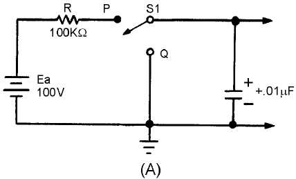
A sawtooth wave can be generated by using an RC network. Possibly the simplest sawtooth
generator is that which is shown in figure 3-38, view (A). Assume that at T0 (view (B)), S1 is placed in
position P. At the instant the switch closes, the applied voltage (Ea) appears at R. C begins to charge to E
a
through R. If S1 remains closed long enough, C will fully charge to Ea. You should remember from
NEETS, Module 2, Alternating Current and Transformers, that a capacitor takes 5 time constants (5TC)
to fully charge. As the capacitor charges to the applied voltage, the rate of charge follows an exponential
curve. If a linear voltage is desired, the full charge time of the capacitor cannot be used because the
exponential curve becomes nonlinear during the first time constant.
Figure 3-38A.—Series RC circuit.


