2-27
through the mutual inductance between the transformer windings of T1. This provides the necessary
180-degree phase shift for the feedback signal. Resistors R
B, RF, and RC provide the base and collector
bias voltage. Capacitor CE bypasses ac variations around emitter resistor RE.
At frequencies above and below the series-resonant frequency of the selected crystal, the impedance
of the crystal increases and reduces the amount of feedback signal. This, in turn, prevents oscillations at
frequencies other than the series-resonant frequency.
Crystal-Controlled Pierce Oscillator
The crystal-controlled PIERCE OSCILLATOR uses a crystal unit as a parallel-resonant circuit. The
Pierce oscillator is a modified Colpitts oscillator. They operate in the same way except that the crystal
unit replaces the parallel-resonant circuit of the Colpitts.
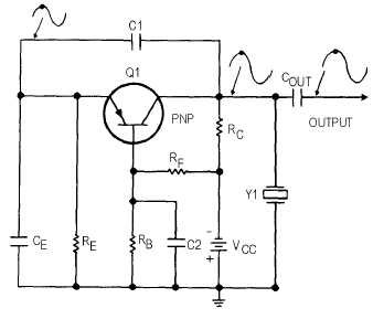
Figure 2-23 shows the common-base configuration of the Pierce oscillator. Feedback is supplied
from the collector to the emitter through capacitor C1. Resistors RB, RC, and RF provide the proper bias
conditions for the circuit and resistor RE is the emitter resistor. Capacitors C1 and CE form a voltage
divider connected across the output. Since no phase shift occurs in the common-base circuit, capacitor C1
feeds back a portion of the output signal to the emitter without a phase shift. The oscillating frequency is
determined not only by the crystal but also by the parallel capacitance caused by capacitors C1 and CE.
This parallel capacitance affects the oscillator frequency by lowering it. Any change in capacitance of
either C1 or CE changes the frequency of the oscillator.
Figure 2-23.—Pierce oscillator, common-base configuration.
Figure 2-24 shows the common-emitter configuration of the Pierce oscillator. The resistors in the
circuit provide the proper bias and stabilization conditions. The crystal unit and capacitors C1 and C2
determine the output frequency of the oscillator. The signal developed at the junction between Y1 and C1
is 180 degrees out of phase with the signal at the junction between Y1 and C2. Therefore, the signal at the
Y1-C1 junction can be coupled back to the base of Q1 as a regenerative feedback signal to sustain
oscillations.


