2-31
FREQUENCY MULTIPLICATION
FREQUENCY MULTIPLIERS are special class C amplifiers that are biased at 3 to 10 times the
normal cutoff bias. They are used to generate a frequency that is a multiple (harmonic) of a lower
frequency. Such circuits are called frequency multipliers or harmonic generators.
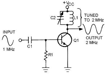
Figure 2-26 illustrates a frequency multiplier known as a FREQUENCY DOUBLER or SECOND
HARMONIC GENERATOR. As illustrated, the input is 1 megahertz and the output is 2 megahertz, or
twice the input frequency. In other words, the second harmonic of 1 megahertz is 2 megahertz. The third
harmonic (frequency tripler) would be 3 megahertz, or 3 times the input signal. The fourth harmonic
(quadruplet) would be 4 megahertz, or 4 times the 1-megahertz input signal. The fourth harmonic
generator (frequency quadruplet) is normally as high in multiplication as is practical, because at
harmonics higher than the fourth, the output diminishes to a very weak output signal.
Figure 2-26.—Frequency doubler.
Frequency multipliers are operated by the pulses of collector current produced by a class C amplifier.
Although the collector current flows in pulses, the alternating collector voltage is sinusoidal because of
the action of the tank circuit. When the output tank circuit is tuned to the required harmonic, the tank
circuit acts as a filter, accepting the desired frequency and rejecting all others.
Figure 2-27 illustrates the waveforms in a typical doubler circuit. You can see that the pulses of
collector current are the same frequency as the input signal. These pulses of collector current energize the
tank circuit and cause it to oscillate at twice the base signal frequency. Between the pulses of collector
current, the tank circuit continues to oscillate. Therefore, the tank circuit receives a current pulse for every
other cycle of its output.


