3
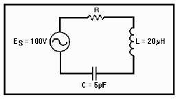
Figure 1A.—Series-resonant circuit.
IN ANSWERING QUESTIONS 1-16
THROUGH 1-21, REFER TO FIGURE 1A.
1-16. What is the resonant frequency for the
circuit?
1. 1.592 MHz
2. 92 MHz
3. 159.2 MHz
4. 1,592 MHz
1-17. What is the value of inductive reactance?
1. 1.97 ohms
2. 97 ohms
3. 199.7 ohms
4. 1,997 ohms
1-18. If the resonant frequency is 7.96 MHz,
what is the value of capacitive reactance?
1. 500 ohms
2. 1,000 ohms
3. 2,000 ohms
4. 4,000 ohms
IN ANSWERING QUESTIONS 1-19
THROUGH 1-21, ASSUME THE SOURCE
FREQUENCY IN FIGURE 1A IS ABOVE
THE RESONANT FREQUENCY. SELECT
THE ANSWERS THAT DESCRIBE HOW AN
ABOVE-RESONANCE FREQUENCY WILL
CAUSE THE CIRCUIT CHARACTERISTICS
IN THE QUESTIONS TO RESPOND WHEN
COMPARED TO THEIR VALUES AT
RESONANCE.
1-19. Impedance.
1. Increases
2. Decreases
3. Remains the same
1-20. Current.
1. Increases
2. Decreases
3. Remains the same
1-21. Voltage drops across the reactances.
1. Increases
2. Decreases
3. Remains the same
THIS SPACE LEFT BLANK
INTENTIONALLY.

