3-4
NOTE: Bias arrangements for the following explanations will be termed base-to-emitter. In other
publications you will see the term emitter-to-base used to describe the same bias arrangement.
THE TWO-INPUT, SINGLE-OUTPUT, DIFFERENCE AMPLIFIER
If you combine the common-base and common-emitter configurations into a single transistor
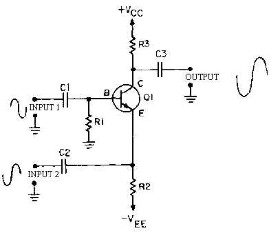
amplifier, you will have a circuit like the one shown in figure 3-2. This circuit is the two-input,
single-output, difference amplifier.
Figure 3-2.—Two-input, single-output, difference amplifier.
In figure 3-2, the transistor has two inputs (the emitter and the base) and one output (the collector).
Remember, the current through the transistor (and therefore the output signal) is controlled by the
base-to-emitter bias. In the circuit shown in figure 3-2, the combination of the two input signals controls
the output signal. In fact, the DIFFERENCE BETWEEN THE INPUT SIGNALS determines the
base-to-emitter bias.
For the purpose of examining the operation of the circuit shown in figure 3-2, assume that the circuit
has a gain of -10. This means that for each 1-volt change in the base-to-emitter bias, there would be a
10-volt change in the output signal. Assume, also, that the input signals will peak at 1-volt levels (+1 volt
for the positive peak and -1 volt for the negative peak). The secret to understanding this circuit (or any
transistor amplifier circuit) is to realize that the collector current is controlled by the base-to-emitter bias.
In other words, in this circuit the output signal (the voltage developed across R3) is determined by the
difference between the voltage on the base and the voltage on the emitter.
Figure 3-3 shows this two-input, single-output amplifier with input signals that are equal in
amplitude and 180 degrees out of phase. Input number one has a positive alternation when input number
two has a negative alternation and vice versa.


