3-3
with the differential amplifier: It operates on the difference between two inputs. However, the difference
amplifier has only one output while the differential amplifier can have two outputs.
By now, you should be familiar with some amplifier circuits, which should give you an idea of what
a difference amplifier is like. In NEETS, Module 7, you were shown the basic configurations for transistor
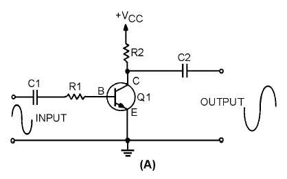
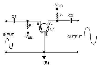
amplifiers. Figure 3-1 shows two of these configurations: the common emitter and the common base.
In view (A) of figure 3-1 a common-emitter amplifier is shown. The output signal is an amplified
version of the input signal and is 180 degrees out of phase with the input signal. View (B) is a common-
base amplifier. In this circuit the output signal is an amplified version of the input signal and is in phase
with the input signal. In both of these circuits, the output signal is controlled by the base-to-emitter bias.
As this bias changes (because of the input signal) the current through the transistor changes. This causes
the output signal developed across the collector load (R2) to change. None of this information is new, it is
just a review of what you have already been shown regarding transistor amplifiers.
Figure 3-1A.—Common-emitter and common-base amplifiers.
Figure 3-1B.—Common-emitter and common-base amplifiers.


