3-52
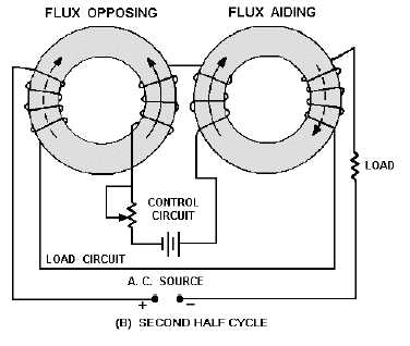
Figure 3-37B.—Toroidal saturable-core reactor. SECOND HALF CYCLE
Figures 3-36 and 3-37 both represent practical, workable saturable-core reactors. Circuits similar to
these are actually used to control lighting in auditoriums or electric industrial furnaces. These circuits are
sometimes referred to as magnetic amplifiers, but that is NOT technically correct. A magnetic amplifier
differs from a saturable-core reactor in one important aspect: A magnetic amplifier has a rectifier in
addition to a saturable-core reactor.
Q-42.
If the permeability of the core of a coil increases, what happens to (a) inductance and (b) true
power in the circuit?
Q-43.
What happens to the permeability of an iron core as the current increases from the operating
point to a large value?
Q-44.
If two coils are wound on a single iron core, what will a change in current in one coil cause in
the other coil?
Q-45.
What symbol in figure 3-33 indicates a saturable core connecting two windings?
SIMPLIFIED MAGNETIC AMPLIFIER CIRCUITRY
If the saturable-core reactor works, why do we need to add a rectifier to produce a magnetic
amplifier? To answer this question, recall that in NEETS, Module 2—Introduction to Alternating Current
and Transformers, you were told about hysteresis loss. Hysteresis loss occurs because the a.c. applied to a
coil causes the tiny molecular magnets (or electron-spin directions) to realign as the polarity of the a.c.
changes. This realignment uses up power. The power that is used for realignment is a loss as far as the
rest of the circuit is concerned. Because of this hysteresis loss in the saturable-core reactor, the power
gain is relatively low. A rectifier added to the load circuit will eliminate the hysteresis loss and increase
the gain. This is because the rectifier allows current to flow in only one direction through the load coils.
A simple half-wave magnetic amplifier is shown in figure 3-38. This is a half-wave magnetic
amplifier because it uses a half-wave rectifier. During the first half cycle of the load voltage, the diode
conducts and the load windings develop load flux as shown in view (A) by the dashed-line arrows. The


