3-53
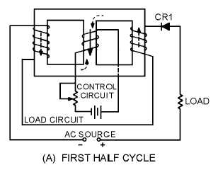
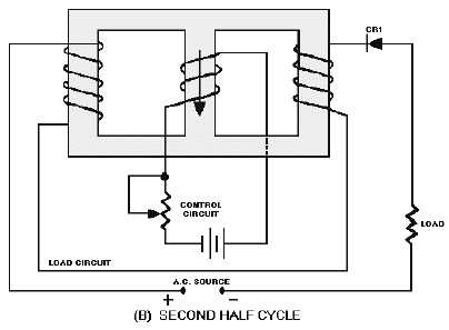
load flux from the two load coils cancels and has no effect on the control flux. During the second half
cycle, the diode does not conduct and the load coils develop no flux, as shown in view (B). The load flux
never has to reverse direction as it did in the saturable-core reactor, so the hysteresis loss is eliminated.
Figure 3-38A.—Simple half-wave magnetic amplifier. FIRST HALF CYCLE
Figure 3-38B.—Simple half-wave magnetic amplifier. SECOND HALF CYCLE
The circuit shown in figure 3-38 is only able to use half of the load voltage (and therefore half the
possible load power) since the diode blocks current during half the load-voltage cycle. A full-wave
rectifier used in place of CR1 would allow current flow during the entire cycle of load voltage while still
preventing hysteresis loss.
Figure 3-39 shows a simple full-wave magnetic amplifier. The bridge circuit of CR1, CR2, CR3,
CR4 allows current to flow in the load circuit during the entire load voltage cycle, but the load current is
always in the same direction. This current flow in one direction prevents hysteresis loss.


