3-42
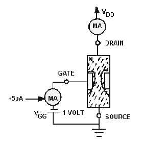
Figure 3-49.—JFET input impedance.
With a VGG of 1 volt, the microammeter reads .5 microamps. Applying Ohm's law (1V ÷ .5 µA)
illustrates that this very small amount of current flow results in a very high input impedance (about 2
megohms). By contrast, a bipolar transistor in similar circumstances would require higher current flow
(e.g., .1 to
-
1 mA), resulting in a much lower input impedance (about 1000 ohms or less). The higher
input impedance of the JFET is possible because of the way reverse-bias gate voltage affects the cross-
sectional area of the channel.
The preceding example of JFET operation uses an N-channel JFET. However, a P-channel JFET
operates on identical principles. The differences between the two types are shown in figure 3-50.
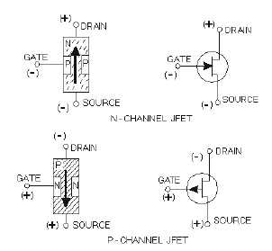
Figure 3-50.—JFET symbols and bias voltages.
Because the materials used to make the bar and the gate are reversed, source voltage potentials must
also be reversed. The P-channel JFET therefore requires a positive gate voltage to be reverse biased, and
current flows through it from drain to source.