3-38
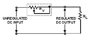
Figure 3-41.—Series voltage regulator.
You should be able to see that as the input voltage decreases, the resistance of the variable resistor Rv
decreases almost simultaneously, thereby compensating for the voltage drop. Since there is a smaller
voltage drop across Rv, the output voltage remains almost constant. Voltage fluctuations within the circuit
occur in microseconds.
Shunt Voltage Regulator
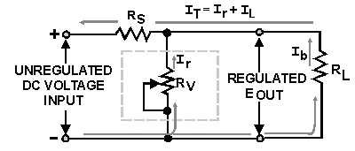
The diagram in figure 3-42 represents a shunter voltage regulator. Notice that variable resistor Rv is
in parallel with the load resistance RL and that fixed resistor RS is in series with the load resistance. You
already know the voltage drop across a fixed resistor remains constant unless there is a variation (increase
or decrease) in the current through it.
In a shunt regulator as shown in figure 3-42, output voltage regulation is determined by the current
through the parallel resistances of the regulating device (Rv), the load resistance (RL), and the series
resistor (RS). For now, assume that the circuit in figure 3-42 is operating under normal conditions, that the
input is 120 volts dc, and that the desired regulated output is 100 volts dc. For a 100-volt output to be
maintained, 20 volts must be dropped across the series resistor (RS). If you assume that the value of RS is
2 ohms, then you must have 10 amperes of current through Rv and RL. (Remember: E = IR.) If the values
of the resistance of Rv and RL are equal, then 5 amperes of current will flow through each resistance (Rv
and RL).
Figure 3-42.—Shunt voltage regulator.
Now, if the load resistance (RL) increases, the current through RL will decrease. For example, assume
that the current through RL is now 4 amperes and that the total current through RS is 9 amperes. With this
drop in current, the voltage drop across RS is 18 volts; consequently, the output of the regulator has
increased to 102 volts. At this time, the regulating device (Rv) decreases in resistance, and 6 amperes of
current flows through this resistance (Rv). Thus, the total current through RS is once again 10 amperes (6
amperes across Rv, 4 amperes through RL); therefore, 20 volts will be dropped across RS causing the
output to decrease back to 100 volts.


