3-37
There are two basic types of voltage regulators, series and shunt. Whether a voltage regulator is
classified as series or shunt depends on the location or position of the regulating element(s) in relation to
the circuit load resistance.
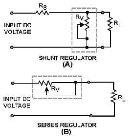
Figure 3-40 illustrates the two basic types of voltage regulators. In actual practice the circuitry of
regulating devices may be quite complex. We use the simplified drawings in the figure to emphasize that
there are two basic types of voltage regulators. Broken lines highlight the differences between the series
and shunt regulators.
Figure 3-40.—Series and shunt regulators.
The schematic in view (A) is that of a shunt-type regulator. It is called a shunt-type regulator because
the regulating device is connected in parallel with the load resistance. This is a characteristic of all shunt-
type regulators. The schematic in view (B) is that of a series regulator. It is called a series regulator
because the regulating device is connected in series with the load resistance.
Series Voltage Regulator
Figure 3-41 illustrates the principle of series voltage regulation. As you study the figure, notice that
the regulator is in series with the load resistance and that all current passes through the regulator. In this
example, variable resistor Rv is used for regulation. Examine the circuit to determine how the regulator
functions. When the input voltage increases, the output voltage also increases. However, since the voltage
regulator device (Rv) senses this change, the resistance of the regulating device increases and results in a
greater voltage drop through Rv. This causes the output voltage to decrease to normal or, for all practical
purposes, to remain constant.


